This tutorial is for Mastercam version 3.21, a DOS-based program that was included on many Centroid controls shipped between 1994 and 2001.
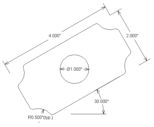
We will use Mastercam to program an irregular-shaped pocket with the profile shown here.
The pocket is to be milled to a depth of 0.375", using a 1/4" end mill, in three passes of 0.125".
The 1" circle in the center of the pocket is an island, to be left standing.
The undimensioned fillet radii may be ignored. They merely represent the cutter radius.
Assume the center island has a bolt hole in its center, which can be used to locate the part.
Since the center of the island can be located, and it is also the center of the symmetric pocket, we will use it as the part zero location (the coordinate origin).
It will be simplest to draw the rectangle aligned with the X and Y axes, then rotate it 30 degrees to match the drawing.
Before drawing the outline of the pocket and island, we should set the drawing Z coordinate to match the bottom of the pocket. This will save some effort later.
• Select Z (in the lower part of the menu on the left, initially shown with a value of 0.0000).
• Type -0.375 and press Enter. It may take a moment for Mastercam to respond to your typing and display it on the screen; be patient.
Now we are ready to draw the pocket outline.
• Select Create, Rectangle, 2 points.
Mastercam will prompt you for the lower left corner of the rectangle.
• Type -2, -1 and press Enter.
Mastercam will prompt you for the upper right corner of the rectangle.
• Type 2,1 and press Enter.
• Press Alt-F1 to fit the screen to the newly created rectangle.
• Press ESC twice to return to the "Create" menu.
• Select Arc, Polar.
Mastercam will prompt you for the arc center point.
• Select Endpoint, then click on the lower left corner of the rectangle.
Mastercam will prompt you for the arc radius.
• Type 0.5 and press Enter.
Mastercam will prompt you for the start angle.
• Press Enter to accept the default of 0.
Mastercam will prompt you for the end angle.
• Type 90 and press Enter.
The selected arc will appear on the screen, and Mastercam will prompt for another arc center.
• Click near the upper left corner.
Mastercam will prompt you for the arc radius.
• The default is now 0.5, so just press Enter.
Mastercam will prompt you for the start angle.
• Type 270 and press Enter.
Mastercam will prompt you for the end angle.
• Type 0 and press Enter.
• Repeat this procedure in the upper right corner (start = 180, end = 270), and in the lower right corner (start = 90, end = 180).
• Select MAIN MENU.
• Select Modify, Trim, 1 object.
Mastercam will prompt you for the object to trim.
• Click on the top line, somewhere near the center (you must click on the part of the line you plan to keep; not the part you plan to trim away!).
Mastercam will prompt you for the object to trim to.
• Click on the upper left arc.
• Repeat these steps to trim the top line to the upper right arc, and to trim each of the other three sides to their respective pairs of arcs.
• Select MAIN MENU.
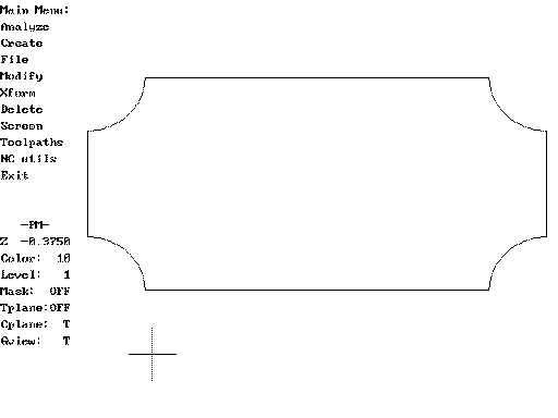
Your drawing should look something like this:
• Select Create, Arc, pt Dia cir.
Mastercam will prompt you for the circle center.
• Type 0,0 and press Enter.
Mastercam will prompt you for the circle diameter.
• Type 1 and press Enter.
• Select MAIN MENU.
Mastercam cannot use a whole circle as part of a toolpath. Thus we will need to break this circle into two (or more) arcs.
• Select Modify, Break, 2 pieces.
Mastercam will prompt for an entity to break.
• Click anywhere on the perimeter of the circle.
Mastercam will prompt for a break point.
• On the point selection menu, select Midpoint, then click anywhere on the circle again. Mastercam will break the circle at the 9:00 position. There was already an implicit start/end point at the 3:00 position, so we now have two equal pieces.
• Select MAIN MENU.
Now we are ready to rotate the geometry to match the drawing.
• Select Xform.
Verify that "Number of steps" displayed at the bottom of the screen is 1.
• Select Delete, so that the original (unrotated) geometry is not left behind.
• Select Rotate, All, Entities, Origin.
• Type 30 and press Enter.
• Press Alt-F1 again to fit the screen around the rotated geometry.
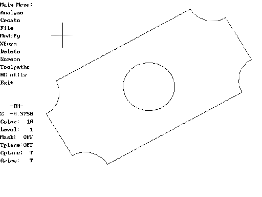
Your completed drawing should look something like this:
We should now save the drawing before we go on to create the toolpath.
• Select MAIN MENU.
• Select File, Save.
• Type MCT1 and press Enter. This will be our name for the part. Mastercam saves the geometry (the drawing) as a file named MCT1.GE3.
• Select MAIN MENU.
• Select Toolpaths, Pocket
Mastercam will prompt you for a name for the toolpath file.
• Type MCT1 again and press Enter. Mastercam will save the toolpath in a file named MCT1.NCI.
Mastercam will now prompt you to "Chain the outside of the pocket". This means that you will point out what lines and arcs make up the pocket perimeter.
• Select Chain for the Chaining Method.
• Click on the bottom line of the pocket, near the left-hand end. The end of the line at which we start the chain determines whether the finish pass will be a climb cut or conventional cut. Starting at the left end (and going right, counterclockwise around the pocket) will result in a climb cut.
• Select Close. Mastercam will follow the pocket perimeter around until it comes back to the starting point.
• Select End here.
Mastercam will prompt you to chain the first island.
• Select Chain again.
• Click just below the 3:00 point on the island. This will select the lower arc, proceeding clockwise around the circle (and again yielding a climb cut for the finish pass).
• Select Close.
• Select End here.
Mastercam will prompt you to chain the second island.
• Select Done, since there are no more islands.
Mastercam will ask whether you want to "enter at a user-defined point".
• Select No.
Mastercam will now switch to a text screen and prompt for various pocket milling parameters. Note that the depth has already been set correctly, because that was the Z coordinate where we drew the geometry.
• Select the pocket parameters as shown below (lines in bold are ones you will need to change):
                             Pocket parameters

         Cutting method = Zig zag


         Pocket depth = -0.3750
         Roughing angle = 30.000
         Roughing cut spacing = 0.1500
         Entry/exit arc: Radius = 0.2500   Angle = 90.000
         Number of finish passes = 1
         Finishing pass spacing = 0.0100
         Move between finish passes: feedrate
         Machine finish passes at: final depth

       ->Next screen
When you have set all the parameters, select Next screen.
Mastercam will now show a second screen with additional machining parameters.
• Set the values shown in bold:
         Roll cutter around sharp corners

         Tool library: C:\NC\TOOLS.MTL    Material: NONE
         Tool number = 6    Diameter offset = 6    Length offset = 6
         Cutter diameter = 0.2500
         Amount of stock to leave = 0.0000
         Feedrate = 10.0000    Plunge rate = 5.0000    Spindle speed = 2500
         Coolant = off
         Rapid depth = 0.1000
         Starting sequence number = 100    Increment = 2    Program n. = 0
         No rotary axis
         Linear array: Nx, Ny = 1 1 Dx, Dy = 0.0000 0.0000
         Depth cuts: Rough: 3 cuts at 0.1250   Finish: 0 cuts at 0.0000
         Home position =  X0.0000 Y0.0000 Z0.0000
         Misc. real [1] = 0.0000    Misc. integer [1] = 0
         Tool Plane: OFF   Tool Origin: OFF
         Display:Tool(static,endpoints,run,delay = 0.00)   Toolpath
       ->Select this line when through setting parameters
• When you have set all the parameters, select the bottom line.
Mastercam will display the resulting toolpath, and will ask you if you want to accept this toolpath segment (making it a permanent part of the NCI toolpath file).
• Answer Yes if everything looks correct.
After a brief pause, Mastercam will again display the Toolpaths menu. Since there are no more operations to add to the program, we are ready to generate the CNC codes (G codes).
• Select End Progrm.
Mastercam will ask you if you want to run the post processor.
• Answer Yes. This will convert the toolpath to CNC codes.
Mastercam will prompt you for the name of the NC file to write.
• Press Enter to accept the default suggestion (MCT1.NC).
• Select MAIN MENU.
• Select Exit and answer Yes.
• If you do not already have the tool set up (tool #6, a ¼" end mill in this example), load the tool, select F1/Setup, F2/Tools, F1/Offsets, and measure the length offset for it.
• If you do not already have the part location set, select F1/Setup, F1/Part, and set the material position for the X, Y, and Z axes. Remember that X0Y0Z0 is at the material surface, on top of the center island.
• Back at the Main Screen, select F8/Graph.
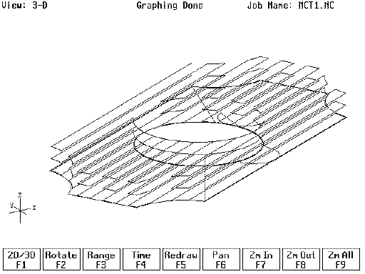
The job is ready to run.
Back to on-line tutorials page
Copyright © 1999 Marc Leonard
You are welcome to print out this tutorial for your
own use and for non-commercial distribution, as long as you include
this copyright message.
Last updated 03-Dec-2006 MBL
![]()