We will cut the motor flange part (from Tutorial #1) in three fixtures. Contrary to the tutorial, though, we will be using two separate tools: a 3/8" drill for the bolt hole pattern and a 1/2" end mill for the pocket and frame. We do not wish to change to the second tool until we have cut all three parts with the first one.
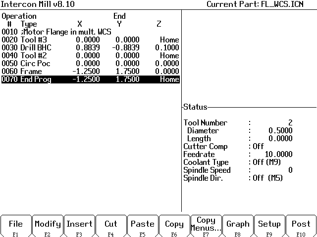
In one fixture, the part program would be as follows:
Tool #3 is the 3/8" drill; tool #2 is the 1/2" end mill. We can bolt the part down through the drilled holes and remove the outer clamps at the same time that we change tools, allowing the end mill to cut the outside frame.
We will now modify the part program for multiple coordinate systems. We will use the first three coordinate systems -- G54, G55, and G56 -- for our three fixtures. We will drill the bolt holes moving from left to right (G54, then G55, then G56). Then we will mill the pockets and frames returning right to left (G56, G55, then G54).
Before the first cut we need to select our first coordinate system. To select coordinate systems, we simply use the "Insert M&G Code" feature to put G54, G55, G56, etc. into the CNC program.
At operation number 30, press F3/Insert, F6/Other, F6/M&G Code.
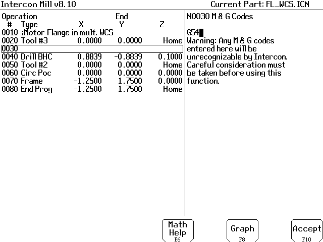
Type G54 and press F10.
Press ESC to leave Insert mode.
Now we want to repeat the drilling pattern in the second and third coordinate systems, before we change to Tool #2.
At operation number 50, press F3/Insert, F6/Other, F6/M&G Code.
Type G55 and press F10.
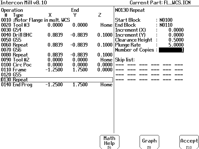
Press F9/Subpgm, F2/Repeat. We will be repeating just the bolt hole circle (operation 40). The X and Y increments will both be zero. This is because we will be using different part zeros to separate the parts, rather than changing the X-Y coordinates with respect to part zero.
Enter a Clearance Height different from your default canned cycle clearance. In this case we will use 0.5000 instead of 0.1000. This ensures a move to the correct Z height in the next coordinate system.
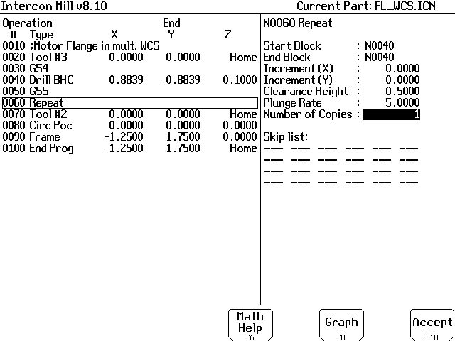
Press F10 to accept the Repeat.
Now on to the third fixture....
Press F6/Code, F6/Other. Type G56 and press F10.
Press F9/Subpgm, F2/Repeat. All the parameters should be the same as the previous Repeat, so you need only press F10 to accept.
Press ESC to leave Insert mode.
We can stay in G56 (the third coordinate system) for the first pocket and frame, so there is no need to insert a coordinate system code immediately after the tool change.
At operation 120 (previously the End of Program) press F3/Insert, F6/Other, F6/M&G Code. Type G55 and press F10.
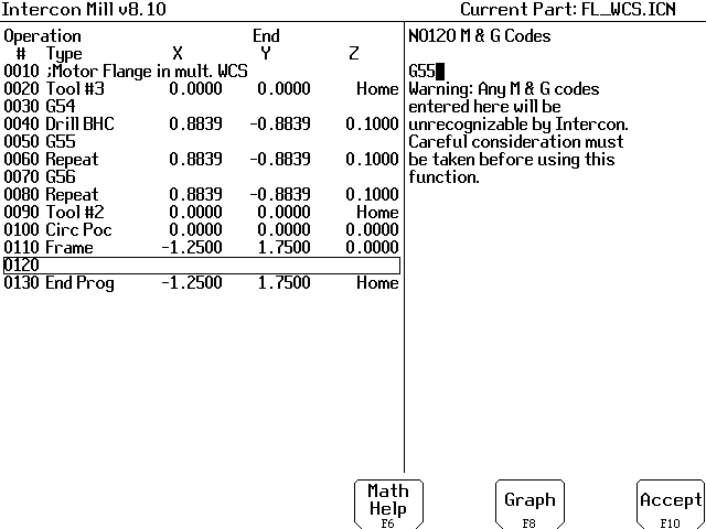
Press F9/Subpgm, F2/Repeat. We now want to repeat the pocket and frame (operations 100 and 110) on the second fixture. Enter the Repeat parameters, again changing the Clearance Height to a number different from the default, and press F10.
Press F6/Other, F6/Code. Type G54 and press F10.
Press F9/Subpgm, F2/Repeat. All the parameters are correct from the previous repeat, so press F10.
Press ESC to leave insert mode.
The completed program should look like this:
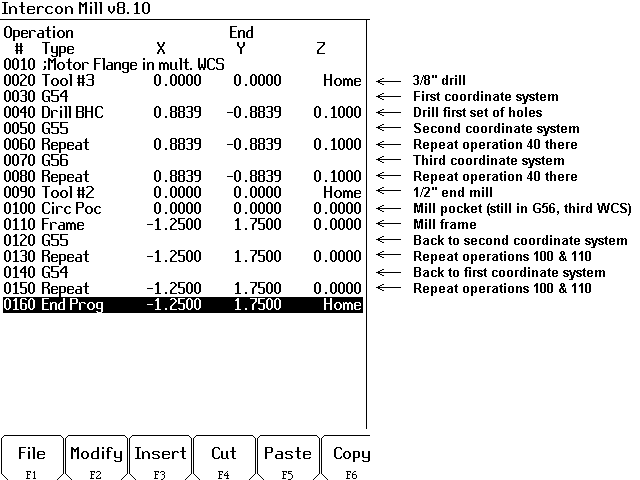
Note that the Intercon graphics screen (F8/Graph while working on the program) might not show three separate parts. This is because we have net yet set up the different locations of the three work coordinate systems. If two or more coordinate systems are in the same place, then the parts will appear overlaid on top of each other. This is not a problem.
Press F10/Post to save the program and post to G codes.
If you are actually going to cut the parts, you must measure length offsets for Tools 2 and 3 in the Offset Library, then use the Part Setup screen to set part zeros in each of the three coordinate systems G54, G55, and G56. Press F6/Prev WCS and F7/Next WCS as needed to change coordinate systems. Note that the currently selected coordinate system is always displayed in the upper left corner of the screen.
If you are working offline, or just want to see a graphic view of the parts without actually cutting them, press F9/WCS, then F2/Origin (from the Part Setup screen). Type in part positions as follows and press F10.

Press ESC until you are back at the CNC7 Main Screen, then press F8/Graph. You should see three separate parts, spaced apart by the WCS origins you entered.

Back to on-line tutorials page
Copyright © 2007 Marc Leonard
You are welcome to print out this tutorial for your
own use and for non-commercial distribution, as long as you include
this copyright message.
Last updated 21-Oct-2007 MBL
![]()